<< Lesson 12Lesson 14 >>
Welcome to my number thirteen in my series of WebGL tutorials! In it,
we’ll cover per-fragment lighting, which is harder work for the graphics
card than the per-vertex lighting we’ve been doing so far, but gives
much more realistic results. We’ll also look at how you can switch the
shaders used by your code by changing which WebGL program object is in
use.
Here’s what the lesson looks like when run on a browser that supports WebGL:
Click here and you’ll see the live WebGL version, if you’ve got a browser that supports it; here’s how to get one if you don’t. You’ll see a sphere and cube orbiting; both will probably be white for a few moments while the textures load, but once that’s done you should see that the sphere is the moon and the cube a (not-to-scale) wooden crate; the scene is similar to the one we had for lesson 12, but we’re closer to the orbiting objects so that you can see more clearly what they look like. As before, both are illuminated by a point light source that is in between them, and if you want to change the light’s position, colour, etc., there are fields beneath the WebGL canvas, along with checkboxes to switch lighting on and off, to switch between per-fragment and per-pixel lighting, and to use or not use the textures.
Try toggling the per-fragment lighting on and off. You should be able to see the difference on the crate pretty easily; the centre is obviously brighter with it switched on. The difference with the moon is more subtle; the edges where the lighting fades out are smoother and less ragged with per-fragment lighting than they are with per-vertex. You will probably be able to see this more easily if you switch off the textures.
More on how it all works below…
The usual warning: these lessons are targeted at people with a reasonable amount of programming knowledge, but no real experience in 3D graphics; the aim is to get you up and running, with a good understanding of what’s going on in the code, so that you can start producing your own 3D Web pages as quickly as possible. If you haven’t read the previous tutorials already, you should probably do so before reading this one — here I will only explain the new stuff. The lesson is based on lesson 12, so you should make sure that you understand that one (and please do post a comment on that post if anything’s unclear about it!)
There may be bugs and misconceptions in this tutorial. If you spot anything wrong, let me know in the comments and I’ll correct it ASAP.
There are two ways you can get the code for this example; just “View Source” while you’re looking at the live version, or if you use GitHub, you can clone it (and the other lessons) from the repository there.
Let’s kick off by describing exactly why it’s worth taking up more graphics processor power by coding per-fragment lighting. 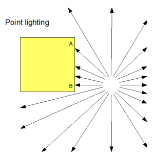 You may remember the diagram to the left from lesson 7.
As you know, the brightness of a surface is determined by the angle
between its normal and the incoming rays of light from the light source.
Now, so far, our lighting has been calculated in the vertex shader by
combining the normals specified for each vertex with the lighting
direction from it. This has provided a light-weighting factor, which
we’ve passed from the vertex shader to the fragment shader in a varying
variable, and there used to vary the brightness of the colour of the
fragment appropriately. This light-weighting factor, like all varying
variables, will have been linearly interpolated by the WebGL system to
provide values for it for the fragments that lie between the vertices;
so, in the diagram, B will be quite bright because the light is parallel
with the normal there, A will be dimmer because the light is reaching
it at more of an angle, and points in between will shade smoothly
between bright and dim. This will look just right.
You may remember the diagram to the left from lesson 7.
As you know, the brightness of a surface is determined by the angle
between its normal and the incoming rays of light from the light source.
Now, so far, our lighting has been calculated in the vertex shader by
combining the normals specified for each vertex with the lighting
direction from it. This has provided a light-weighting factor, which
we’ve passed from the vertex shader to the fragment shader in a varying
variable, and there used to vary the brightness of the colour of the
fragment appropriately. This light-weighting factor, like all varying
variables, will have been linearly interpolated by the WebGL system to
provide values for it for the fragments that lie between the vertices;
so, in the diagram, B will be quite bright because the light is parallel
with the normal there, A will be dimmer because the light is reaching
it at more of an angle, and points in between will shade smoothly
between bright and dim. This will look just right.
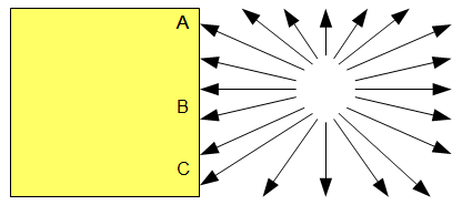 But
now imagine that the light is higher up, as in the diagram to the
right. A and C will be dim, as the light reaches them at an angle. We
are calculating lighting at the vertices only, and so point B will have
the average brightness of A and C, so it will also be dim. This is, of
course, wrong — the light is parallel the surface’s normal at B, so it
should actually be brighter than either of them. So, in order to
calculate the lighting at fragments between vertices, we obviously need
to calculate it separately for each fragment.
But
now imagine that the light is higher up, as in the diagram to the
right. A and C will be dim, as the light reaches them at an angle. We
are calculating lighting at the vertices only, and so point B will have
the average brightness of A and C, so it will also be dim. This is, of
course, wrong — the light is parallel the surface’s normal at B, so it
should actually be brighter than either of them. So, in order to
calculate the lighting at fragments between vertices, we obviously need
to calculate it separately for each fragment.
Calculating the lighting for each fragment means that for each one we need its location (to work out the direction of the light) and its normal; we can get these by passing them from the vertex shader to the fragment shader. They will both be linearly interpolated, so the positions will lie along a straight line between the vertices, and the normals will vary smoothly. That straight line is just what we want, and because the normals at A and C are the same, the normals will be the same for all of the fragments, which is perfect too.
So, that all explains why the cube in our web page looks better and more realistic with per-fragment lighting. But there’s another benefit, and this is that it gives a great effect to shapes made up of flat planes that are meant to approximate curved surfaces, like our sphere. If the normals at two vertices are different, then the smoothly-changing normals at the intervening fragments will give the effect of a curving surface. When considered in this way, per-fragment lighting is a form of what is called Phong shading, and this picture on Wikipedia shows the effect better than I could explain in several thousand words. You can see this in the demo; if you use per-vertex lighting, you can see that the edge of the shadow (where the point light stops having an effect and the ambient lighting takes over) looks a bit “ragged”. This is because the sphere is made up of many triangles, and you can see their edges. When you switch on per-fragment lighting, you can see that the edge of this transition is smoother, giving a better effect of roundness.
Right, that’s the theory out of the way — let’s take a look at the
code! The shaders are at the top of the file, so lets take a look at
them first. Because this example uses either per-vertex or per-fragment
lighting, depending on the setting of the “per-vertex” checkbox, it has
vertex and fragment shaders for each kind (it would be possible to
write shaders that could do both, but they would be harder to read).
The way that we switch between them is something we’ll come to later,
but for now you should just note that we distinguish between them by
using different id tags when defining them as scripts in
the web page. The first to appear are the shaders for per-vertex
lighting, and they’re exactly the same as the ones we’ve been using
since lesson 7, so I will just show their script tags so that you can match them up with what you will see if you’re following through in the file:
<script id="per-vertex-lighting-fs" type="x-shader/x-fragment">
<script id="per-vertex-lighting-vs" type="x-shader/x-vertex">
Next comes the fragment shader for per-fragment lighting.
<script id="per-fragment-lighting-fs" type="x-shader/x-fragment">
  #ifdef GL_ES
  precision highp float;
  #endif

  varying vec2 vTextureCoord;
  varying vec4 vTransformedNormal;
  varying vec4 vPosition;

  uniform bool uUseLighting;
  uniform bool uUseTextures;

  uniform vec3 uAmbientColor;

  uniform vec3 uPointLightingLocation;
  uniform vec3 uPointLightingColor;

  uniform sampler2D uSampler;

  void main(void) {
    vec3 lightWeighting;
    if (!uUseLighting) {
      lightWeighting = vec3(1.0, 1.0, 1.0);
    } else {
      vec3 lightDirection = normalize(uPointLightingLocation - vPosition.xyz);

      float directionalLightWeighting = max(dot(normalize(vTransformedNormal.xyz), lightDirection), 0.0);
      lightWeighting = uAmbientColor + uPointLightingColor * directionalLightWeighting;
    }

    vec4 fragmentColor;
    if (uUseTextures) {
      fragmentColor = texture2D(uSampler, vec2(vTextureCoord.s, vTextureCoord.t));
    } else {
      fragmentColor = vec4(1.0, 1.0, 1.0, 1.0);
    }
    gl_FragColor = vec4(fragmentColor.rgb * lightWeighting, fragmentColor.a);
  }
</script>
You can see that this is very similar to the vertex shaders that we’ve been using so far; it does exactly the same calculations to work out the direction of the light and to then combine that with the normal to calculated a light weighting. The difference is that the inputs to this calculation now come from varying variables rather than per-vertex attributes, and the resulting weighting is immediately combined with the texture colour from the sample rather than passed out for processing later. It’s also worth noting that we have to normalise the varying variable that contains the interpolated normal; normalising, you will remember, adjusts a vector so that its length is one unit. This is because interpolating between two length-one vectors does not necessarily give you a length-one vector, just a vector that points in the right direction. Normalising them fixes that. (Thanks to Glut for pointing that out in the comments.)
Because all of the heavy lifting is being done by the fragment shader, the vertex shader for per-fragment lighting is really simple:
<script id="per-fragment-lighting-vs" type="x-shader/x-vertex">
  attribute vec3 aVertexPosition;
  attribute vec3 aVertexNormal;
  attribute vec2 aTextureCoord;

  uniform mat4 uMVMatrix;
  uniform mat4 uPMatrix;
  uniform mat4 uNMatrix;

  varying vec2 vTextureCoord;
  varying vec4 vTransformedNormal;
  varying vec4 vPosition;

  void main(void) {
    vPosition = uMVMatrix * vec4(aVertexPosition, 1.0);
    gl_Position = uPMatrix * vPosition;
    vTextureCoord = aTextureCoord;
    vTransformedNormal = uNMatrix * vec4(aVertexNormal, 1.0);
  }
</script>
We still need to work out the vertex’s location after the application of the model-view matrix and multiply the normal by the normal matrix, but now we just stash them away in varying variables for later use in the fragment shader.
That’s it for the shaders! The rest of the code will be pretty familiar from the previous lessons, with one exception. So far, we’ve only used one vertex shader and one fragment shader per WebGL page. This one uses two pairs, one for per-vertex lighting and one for per-fragment lighting. Now, you may remember from lesson 1 that the WebGL program object that we use to pass our shader code up to the graphics card can have only one fragment shader and one vertex shader. What this means is that we need to have two programs, and switch which one we use based on the setting of the “per-fragment” checkbox.
The way we do this is simple; our initShaders function is changed to look like this:
  var currentProgram;
  var perVertexProgram;
  var perFragmentProgram;
  function initShaders() {
    perVertexProgram = createProgram("per-vertex-lighting-fs", "per-vertex-lighting-vs");
    perFragmentProgram = createProgram("per-fragment-lighting-fs", "per-fragment-lighting-vs");
  }
So, we have two programs in separate global variables, one for per-vertex lighting and one for per-fragment, and a separate currentProgram variable to store the one that’s currently in use. The createProgram we use to create them is simply a parameterised version of the code we used to have in initShaders, so I won’t duplicate it here.
We then switch in the appropriate program right at the start of the drawScene function:
  function drawScene() {
    gl.viewport(0, 0, gl.viewportWidth, gl.viewportHeight);
    gl.clear(gl.COLOR_BUFFER_BIT | gl.DEPTH_BUFFER_BIT);

    perspective(45, gl.viewportWidth / gl.viewportHeight, 0.1, 100.0);

    var perFragmentLighting = document.getElementById("per-fragment").checked;
    if (perFragmentLighting) {
      currentProgram = perFragmentProgram;
    } else {
      currentProgram = perVertexProgram;
    }
    gl.useProgram(currentProgram);
We have to do this before anything else because when we do drawing code (for example setting uniforms or attaching buffers of per-vertex attributes to attributes) we need the current program to be appropriately set up, as otherwise we might use the wrong program:
    var lighting = document.getElementById("lighting").checked;
    gl.uniform1i(currentProgram.useLightingUniform, lighting);
You can see that this means that for each call to drawScene
we use one and only one program; it differs only between calls. If
you’re wondering whether or not you could use different shader programs
at different times within drawScene, so that different
parts of the scene were drawn with different ones — perhaps some of your
scene might use per-vertex lighting and some per-pixel — the answer is
yes! It wasn’t needed for this example, but is perfectly valid and can
be useful.
Anyway — with that explained, that’s it for this lesson! You now know how to use multiple programs to switch shaders, and how to code per-pixel lighting. Next time we’ll look at the last bit of lighting that was mentioned in lesson 7: specular highlights.
Acknowledgments: As before, the texture-map for the moon comes from NASA’s JPL website, and the code to generate a sphere is based on this demo, which was originally by the WebKit team. Many thanks to both!


Another great lesson, your explanations are so easy to understand. I really wish a resource like this was available a year ago, it would certainly have meant a few less headaches!
Thanks, Paul! Hopefully it can save a few headaches for people in the future, at least. Or alternatively they can use GLGE and not have to worry about it ;-)
Hi! There is one thing I don’t understand. Fragment shader is for pixel calculations and vertex shader is for calculations vertextes of polygons? Is vertex shader for calculating every pixel’s position (I mean this on the polygon’s surfaces too?), or only for triange three vertexes? Could you make it clear for me? I am new at Web/OpenGL so…
PS. Very helpful tutorials. Thanks a lot! :)
Cheers, Rabursky
The fragment shader is to calculate the colour of each pixel within a particular polygon. So let’s say you have a triangle; the vertex shader is called three times, one for each vertex, and then the fragment shader is called once for every pixel within the triangle. Is that any clearer?
Ok then. So varying vPosition from vertex shader gives in fragment shader Position of computing pixel or vertex (what vertex?), I mean varying varibles are calculating in vertex shader for each pixel in fragment shader?
I don’t know if you’ve had a chance to look at lesson 2 yet; if not, it might make some of this clearer! Here’s the link: http://learningwebgl.com/blog/?p=134
If that didn’t help, let me try for a better explanation… Let’s imagine that you have a triangle with vertices at (0, 1, 0), (-1, -1, 0), and (1, -1, 0). The vertex shader would, of course, be called once for each of these, and vPosition would be set each time the vertex shader was called.
Next, the WebGL runtime system would work out all of the pixels which would be on the triangle which had those vertices. Each of those would be called a fragment, and the varying variables would be linearly interpolated between vertices to work out an appropriate value for each fragment. An example should probably make that clearer :-) Consider the line between the vertex at (0, 1, 0) and (-1, -1, 0). Imagine that at the size we’re drawing our scene on the screen there were eleven pixels along that line — one at (0, 1, 0), one at (-1, -1, 0), and then nine others in between. The WebGL runtime (or more accurately the underlying stuff) will pass in (0, 1, 0) for vPosition for the pixel/fragment that happens to be exactly on the vertex at (0, 1, 0), but for the one that’s halfway in between the two vertices it will average out all of the values, so vPosition will be (-0.5, 0, 0).
The colours on the triangle in lesson 2 are a great visual illustration of this; the top vertex is red, the bottom right vertex is blue, and the colours are put into a varying variable called vColor, so that means that the pixel in the middle of the right-hand side winds up a mixture or red and blue — that is, purple.
Does that make more sense to you?
Yes, now it is completely clear! Thanks a lot :)
Is there any place in this site I can ask a questions (which may not be connected with topic of current lessons) – of course if it is not a big problem to handle for you?
It’s kinda frustrating when something is not working and you dont know why, or otherwise if sth IS working, but you couldn’t understand it. These may not be a typical questions. You’re a programmer, you know what I mean :)
Cheers!
Yup, I definitely understand that feeling! The best place for general questions about WebGL programming is probably the forums on the Khronos website: http://www.khronos.org/message_boards/viewforum.php?f=34 — I try to help people out when they post problems there, and so do a bunch of other people, many of whom know way more than me :-)
hi,
i guess, you should normalize the interpolated normals in the per-fragment-fragment-shader. because if u linear interpolate 2 nonparallel normalized vectors, the resulting vector won’t be of length 1. and if you furthermore use a dot product on nonnormalized vectors, the resulting angle is different from using it at the normalized versions.
That’s a good point. It doesn’t seem to affect the scene much for this lesson, but I will fix it.
OK, done.
Now there “ragged” shadows are away, i was wandering about them before :)
looks good
If you turn off the textures you may see a dark ring (a dark halo) right where the normals are perpendicular to the light source on the sphere. Do you see it too? And if so is there a way to remove this artifact?
Great lessons btw.
Alright I’ve been trying everything I could for the last few days and the mathematics work out every which way, so it’s likely an optical illusion.
Hi rafe — sorry for the slow reply! I don’t see that effect, so perhaps it is an optical illusion — perhaps worth trying to capture with something like CamStudio? (Though I’ve often found that screen-cap software can add its own artifacts anyway.)
I’ve been playing around with your demos on my mobile (Samsung Galaxy S) and found that the spheres in this example doesn’t get rendered for some reason. Nore do the later examples. I’m using the latest beta of Firefox for Android.
Example 14 works IF none is selected for the texture, but the model is upside down for some reason.
I’m going to assume its some sort of limitation of the PowerVR SGX 540. The Nexus One will likely work just fine.
I altered the texture to 512*512 rather than 512*256 and it worked a treat. would just need to alter the texture coordinates.
Hi CppMonkey — thanks, that’s interesting! Not sure how it could flip the whole model for just one demo, that’s very strange. The requirement for square texures sounds like (as you say) a platform bug; let’s hope it’s something in fixable software rather than unfixable hardware…
It calculates the lightWeighting in ”.
lightWeighting depends on uPointLightingLocation, vPosition and vTransformedNormal. Both vPosition and vTransformedNormal have been calculated in the vertex shader already.
Will it be more efficient to calculate lightWeighting in ”? Because it is computed per vertex rather than per pixel.
Maybe I am missing something. Please clarify. Thanks in advance for your help.
The single quotes seem to “swallow” the info.
Re-post
It calculates the lightWeighting in fragment shader (per-fragment-lighting-fs).
lightWeighting depends on uPointLightingLocation, vPosition and vTransformedNormal. Both vPosition and vTransformedNormal have been calculated in the vertex shader already.
Will it be more efficient to calculate lightWeighting in vertex shader (per-fragment-lighting-fs)? Because it is computed per vertex rather than per pixel.
Maybe I am missing something. Please clarify. Thanks in advance for your help.
@pion — strange about the single quotes!
You are missing one thing — vPosition and vTransformedNormal are varying variables. This means that although values are calculated per-vertex, the per-vertex values are then linearly interpolated to work out a continuous “shade” of values for the fragments that lie in between the vertices. So each fragment gets a slightly different value.
Does that clarify things?
@giles — thanks for the clarification.
What tool do you use to record the WebGL app into YouTube.
Keep up the good work! I learnt a lot from your website.
Thanks again.
No problem! I use CamStudio to record the demos — it’s not very sophisticated, but it works and it’s free.
Hi Giles,
Again, thanks a million times for your wonderful tutorials!
By the way, when can we expect the next one (on picking) ?
On to my question :
1. In practice, what is the limit on the number of programs that are manageable at the same time?
2. Apparently, the ability to switch instantly between programs means that they all share the same frame buffers and generally speaking the same gl runtime state (blending vars etc.) is that correct ?
cheers.
Hi jonathan,
Glad you like the tutorials! As ever, work’s getting in the way (damn that requirement to make money for food ;-) so no ETA on picking. But it will come.
1. The total number of programs you can manage, TBH I don’t know! It might be worth putting together a test and finding out. There is a time overhead to switching, however, which might turn out to be more of a bottleneck in practice than any limit to the total number.
2. Yup. The program determines which shaders are in place, nothing else. Do note, however, that things that you ultimately got from the current shaders — eg. vertex attribute and uniform IDs — do change when you switch.