<< Lesson 6Lesson 8 >>
Welcome to my number seven in my series of WebGL tutorials, based on the part of number 7 in the NeHe OpenGL tutorials that I didn’t go over in lesson 6.
In it, we’ll go over how you add simple lighting to your WebGL pages;
this takes a bit more work in WebGL than it does in OpenGL, but
hopefully it’s all pretty easy to understand.
Here’s what the lesson looks like when run on a browser that supports WebGL:
Click here and you’ll see the live WebGL version, if you’ve got a browser that supports it; here’s how to get one if you don’t. You should see a slowly-spinning cube, with lighting appearing to come from a point that is towards the front (that is, between you and the cube), slightly above and to the right.
You can use the checkbox underneath the canvas to switch off or on
the use of lighting so that you can see what effect it’s having. You
can also change the colour of the directional and ambient lights (more
about precisely what that means later) and the direction of the
directional light. Do try playing with them a bit; it’s particularly
fun to try out special effects with directional lighting RGB values of
greater than one (though if you go much above 5 you lose much of the
texture). Also, just like last time, you can also use the cursor keys to make the box spin around faster or more slowly, and Page Up and Page Down to zoom in and out. We’re using the best texture filter only this time, so the F key no longer does anything.
More on how it all works below…
The usual warning: these lessons are targeted at people with a reasonable amount of programming knowledge, but no real experience in 3D graphics; the aim is to get you up and running, with a good understanding of what’s going on in the code, so that you can start producing your own 3D Web pages as quickly as possible. If you haven’t read the previous tutorials already, you should probably do so before reading this one — here I will only explain the differences between the code for lesson 6 and the new code.
There may be bugs and misconceptions in this tutorial. If you spot anything wrong, let me know in the comments and I’ll correct it ASAP.
There are two ways you can get the code for this example; just “View Source” while you’re looking at the live version, or if you use GitHub, you can clone it (and the other lessons) from the repository there. Either way, once you have the code, load it up in your favourite text editor and take a look.
Before we get into the details of how to do lighting in WebGL, I’ll kick off with the bad news. WebGL has absolutely no built-in support for lighting. Unlike OpenGL, which lets you specify at least 8 light sources and then handles them all for you, WebGL leaves you to do everything yourself. But — and it’s a big “but” — lighting is actually pretty easy once it’s explained. If you’re comfortable with the shader stuff we’ve gone over so far, you’ll have no problems at all with lighting — and having to code your own simple lights as a beginner makes it much easier to understand the kind of code you have to write as when you’re just a little more advanced! After all, OpenGL’s lighting is too basic for really realistic scenes — it doesn’t handle shadows, for example, and it can give quite rough effects with curved surfaces — so anything beyond simple scenes needs hand-coding anyway.
Right. Let’s begin by thinking about what we want from lighting. The aim is to be able to simulate a number of light sources within the scene. These sources don’t need to be visible themselves, but they do need to light up the 3D objects realistically, so that the side of the object that is towards the light is bright, and the side that’s away from the light is dark. So to put it another way, we want to be able to specify a set of light sources, then for each part of our 3D scene we want to work out how the all of the lights affect it. By now I’m sure you’ll know WebGL well enough to realise that this is going to involve doing stuff with shaders. Specifically, what we’ll do in this lesson is write vertex shaders that handle the lighting. For each vertex, we’ll work out how the light affects it, and use that to adjust its colour. We’ll only do this for one light for now; doing it for multiple lights is just a case of repeating the same procedure for each light and adding the results together.
One side note here; because we’re working out the lighting on a per-vertex basis, the effects of the light on the pixels that lie between vertices will be worked out by doing the usual linear interpolation. This means that the spaces between the vertices will be lit up as if they were flat; conveniently, because we’re drawing a cube, this is exactly what we want! For curved surfaces, where you want to calculate the effects of lighting on every pixel independently, you can use a technique called per-fragment (or per-pixel) lighting, which gives much better effects. We’ll look at per-fragment lighting in a future lesson. What we’re doing here is called, logically enough, per-vertex lighting.
OK, on to the next step: if our task is to write a vertex shader that works out how a single light source affects the colour at the vertex, what do we do? Well, a good starting point is the Phong Reflection Model. I found this easiest to understand by starting with the following points:
- While in the real world there is just one kind of light, it’s convenient for graphics to pretend that there are two kinds:
- Light that comes from specific directions and only lights up things that face the direction it’s coming from. We’ll call this directional light.
- Light that comes from everywhere and lights up everything evenly, regardless of which way it faces. This is called ambient light. (Of course, in the real world this is just directional light that has been scattered by reflection from other objects, the air, dust, and so on. But for our purposes, we’ll model it separately.)
- When light hits a surface, it comes off in two different ways:
- Diffusely: that is, regardless of the angle at which it hits the surface, it’s bounced off evenly in all directions. No matter what angle you’re looking at it from, the brightness of the reflected light is governed entirely by the angle at which the light hits the surface — the steeper the angle of incidence, the dimmer the reflection. This diffuse reflection is what we normally think of when we’re thinking of an object that is lit up.
- Specularly: that is, in a mirror-like fashion. The portion of the light that is reflected this way bounces off the surface at the same angle as it hit it. In this case, the brightness of the light you see reflected from the material depends on whether or not your eyes happen to be in the line along which the light was bounced — that is, it depends not only on the angle at which the light hit the surface but on the angle between your line of sight and the surface. This specular reflection is what causes “glints” or “highlights” on objects, and the amount of specular reflection can obviously vary from material to material; unpolished wood will probably have very little specular reflection, and highly-polished metal will have quite a lot.
The Phong model adds a further twist to this four-step system, by saying that all lights have two properties:
- The RGB values for the diffuse light they produce.
- The RGB values for the specular light they produce.
…and that all materials have four:
- The RGB values for the ambient light they reflect.
- The RGB values for the diffuse light they reflect.
- The RGB values for the specular light they reflect.
- The shininess of the object, which determines the details of the specular reflection.
For each point in the scene, the colour is a combination of the colour of the light shining on it, the material’s own colours, and the lighting effects. So, in order to completely specify lighting in a scene according to the Phong model, we need two properties per light, and four per point on the surface of our object. Ambient light is, by its very nature, not tied to any particular light, but we also need a way of storing the amount of the ambient light for the scene as a whole; sometimes it can be easiest to just specify an ambient level for each light source and then add them all up into a single term.
Anyway, once we have all of that information, we can work out colours related to the ambient, directional, and specular reflection of light at every point, and then add them together to work out the overall colour. Here’s an excellent diagram on Wikipedia showing how that works. All our shader needs to do is work out for each vertex the contributions to the vertex’s red, green and blue colours for ambient, diffuse and specular lighting, use them to weight the colour’s RGB components, add them all together, and output the result.
Now, for this lesson, we’re going to keep things simple. We’re only going to consider diffuse and ambient lighting, and will ignore specular. We’ll use the textured cube from the last lesson, and we’ll assume that the colours in the texture are the values to use for both diffuse and ambient reflection. And finally, we will consider only one simple kind of diffuse lighting — the simplest directional kind. It’s worth explaining that with a diagram.
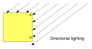 Light that’s coming towards a surface from one direction can be of two
kinds — simple directional lighting that is in the same direction across
the whole scene, and lighting that comes from a single point within the
scene (and is thus at a different angle in different places).
Light that’s coming towards a surface from one direction can be of two
kinds — simple directional lighting that is in the same direction across
the whole scene, and lighting that comes from a single point within the
scene (and is thus at a different angle in different places).
For simple directional lighting, the angle at which the light hits the vertices on a given face — at points A and B on the diagram — is always the same. Think of light from the sun; all rays are parallel.
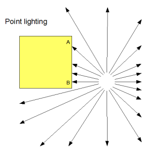 If,
instead, the light is coming from a point within the scene, the angle
the light makes will be different at each vertex; at point A in this
second diagram, the angle is about 45 degrees, whereas at point B it is
about 90 degrees to the surface.
If,
instead, the light is coming from a point within the scene, the angle
the light makes will be different at each vertex; at point A in this
second diagram, the angle is about 45 degrees, whereas at point B it is
about 90 degrees to the surface.
What this means is that for point lighting, we need to work out the direction from which the light is coming for every vertex, whereas for directional lighting we only need to have one value for the directional light source. This makes point lighting a little bit harder, so this lesson will only use simple directional lighting and point lighting will come a later (and shouldn’t be too hard for you to work out on your own anyway :-)
So, now we’ve refined the problem a bit more. We know that all of the light in our scene will be coming in a particular direction, and this direction won’t change from vertex to vertex. This means that we can put it in a uniform variable, and the shader can pick it up. We also know that the effect the light has at each vertex will be determined by the angle it makes with the surface of our object at that vertex, so we need to represent the orientation of the surface somehow. The best way to do this in 3D geometry is to specify the normal vector to the surface at the vertex; this allows us to specify the direction in which the surface is facing as a set of three numbers. (In 2D geometry we could equally well use the tangent — that is, the direction of the surface itself at the vertex — but in 3D geometry the tangent can slope in two directions, so we’d need two vectors to describe it, while the normal lets us use just one vector.)
Once we have the normal, there’s a final piece required before we can write our shader; given a surface’s normal vector at a vertex and the vector that describes the direction the light is coming from, we need to work out how much light the surface will diffusely reflect. This turns out to be proportional to the cosine of the angle between those two vectors; if the normal is 0 degrees (that is, the light is hitting the surface full-on, at 90 degrees to the surface in all directions) then we can say it reflects all of the light. If the light’s angle to the normal is 90 degrees, nothing is reflected. And for everything in between, it follows the cosine’s curve. (If the angle is more than 90 degrees, then we would in theory get negative amounts of reflected light. This is obviously silly, so we actually use the cosine or zero, whichever is the larger.)
Conveniently for us, calculating the cosine of the angle between two
vectors is a trivial calculation, if they both have a length of one;
it’s done by taking their dot product. And even more conveniently, dot products are built into shaders, using the logically-named dot function.
Whew! That was quite a lot of theory to get started with — but now we know that all we need to do to get simple directional lighting working is:
- Keep a set of normal vectors, one for each vertex.
- Have a direction vector for the light.
- In the vertex shader, calculate the dot product of the vertex’s normal and the lighting vector, and weight the colours appropriately, also adding in a component for the ambient lighting
Let’s take a look at how that works in the code. We’ll start at the
bottom and work our way up. Obviously the HTML for this lesson differs
from the last one, because we have all of the extra input fields, but I
won’t bore you with the details there… let’s move up to the JavaScript,
where our first port of call is the initBuffers function.
In there, just after the code that creates the buffer containing the
vertex positions but before the code that does the same for the texture
coordinates, you’ll see some code to set up the normals. This should
look pretty familiar in style by now:
    cubeVertexNormalBuffer = gl.createBuffer();
    gl.bindBuffer(gl.ARRAY_BUFFER, cubeVertexNormalBuffer);
    var vertexNormals = [
      // Front face
       0.0,  0.0,  1.0,
       0.0,  0.0,  1.0,
       0.0,  0.0,  1.0,
       0.0,  0.0,  1.0,

      // Back face
       0.0,  0.0, -1.0,
       0.0,  0.0, -1.0,
       0.0,  0.0, -1.0,
       0.0,  0.0, -1.0,

      // Top face
       0.0,  1.0,  0.0,
       0.0,  1.0,  0.0,
       0.0,  1.0,  0.0,
       0.0,  1.0,  0.0,

      // Bottom face
       0.0, -1.0,  0.0,
       0.0, -1.0,  0.0,
       0.0, -1.0,  0.0,
       0.0, -1.0,  0.0,

      // Right face
       1.0,  0.0,  0.0,
       1.0,  0.0,  0.0,
       1.0,  0.0,  0.0,
       1.0,  0.0,  0.0,

      // Left face
      -1.0,  0.0,  0.0,
      -1.0,  0.0,  0.0,
      -1.0,  0.0,  0.0,
      -1.0,  0.0,  0.0,
    ];
    gl.bufferData(gl.ARRAY_BUFFER, new Float32Array(vertexNormals), gl.STATIC_DRAW);
    cubeVertexNormalBuffer.itemSize = 3;
    cubeVertexNormalBuffer.numItems = 24;
Simple enough. The next change is a bit further down, in drawScene, and is just the code required to bind that buffer to the appropriate shader attribute:
    gl.bindBuffer(gl.ARRAY_BUFFER, cubeVertexNormalBuffer);
    gl.vertexAttribPointer(shaderProgram.vertexNormalAttribute, cubeVertexNormalBuffer.itemSize, gl.FLOAT, false, 0, 0);
Just after this, also in drawScene, is code related to
the fact that we’ve removed the code from lesson 6 that allowed us to
switch between textures, so we have only one texture to use:
gl.bindTexture(gl.TEXTURE_2D, crateTexture);
The next bit is a little more involved. Firstly, we see if the “lighting” checkbox is checked, and set a uniform for our shaders telling them whether or not it is:
    var lighting = document.getElementById("lighting").checked;
    gl.uniform1i(shaderProgram.useLightingUniform, lighting);
Next, if lighting is enabled, we read out the red, green and blue values for the ambient lighting as specified in the input fields at the bottom of the page and push them up to the shaders too:
    if (lighting) {
      gl.uniform3f(
        shaderProgram.ambientColorUniform,
        parseFloat(document.getElementById("ambientR").value),
        parseFloat(document.getElementById("ambientG").value),
        parseFloat(document.getElementById("ambientB").value)
      );
Next, we want to push up the lighting direction:
      var lightingDirection = Vector.create([
        parseFloat(document.getElementById("lightDirectionX").value),
        parseFloat(document.getElementById("lightDirectionY").value),
        parseFloat(document.getElementById("lightDirectionZ").value)
      ]);
      var adjustedLD = lightingDirection.toUnitVector().x(-1);
      var flatLD = adjustedLD.flatten();
      gl.uniform3fv(shaderProgram.lightingDirectionUniform, flatLD);
You can see that we adjust the lighting direction vector before passing it to the shader. The first adjustment, toUnitVector,
scales it up or down so that its length is one; you will remember that
for the cosine of the angle between two vectors to be equal to the dot
product, they both need to be of length one. The normals we defined
earlier all had the correct length, but as the lighting direction is
entered by the user (and it would be a pain for them to have to work out
unit vectors themselves) then we convert this one. The second
adjustment is to multiply the vector by a scalar -1 — that is, to
reverse its direction. This is because we’re specifying the lighting
direction in terms of where the light is going, while the calculations
we discussed earlier were in terms of where the light is coming from.
Once we’ve done that, we pass it up to the shaders using gl.uniform3fv, which puts a three-element Float32Array into a uniform.
The next bit of code is simpler; it just copies the directional light’s colour components up to the appropriate shader uniform:
      gl.uniform3f(
        shaderProgram.directionalColorUniform,
        parseFloat(document.getElementById("directionalR").value),
        parseFloat(document.getElementById("directionalG").value),
        parseFloat(document.getElementById("directionalB").value)
      );
    }
That’s all of the changes in drawScene. Moving up to the key-handling code, there are simple changes to remove the handler for the F key, which we can ignore, and then the next interesting change is in the function setMatrixUniforms,
which you will remember copies the model-view and the projection
matrices up to the shader’s uniforms. We’ve added four lines to copy up
a new matrix, based on the model-view one:
    var normalMatrix = mvMatrix.inverse();
    normalMatrix = normalMatrix.transpose();
    gl.uniformMatrix4fv(shaderProgram.nMatrixUniform, false, new Float32Array(normalMatrix.flatten()));
As you’d expect from something called a normal matrix, it’s used to transform the normals :-) We can’t transform them in the same way as we transform the vertex positions, using the regular model-view matrix, because normals would be converted by our translation as well as our rotation — for example, if we ignore rotation and assume we’ve done an mvTranslate of (0, 0, -5), the normal (0, 0, 1) would become (0, 0, -4), which is not only too long but is pointing in precisely the wrong direction. We could work around that; you may have noticed that in the vertex shaders, when we multiply the 3-element vertex positions by the 4×4 model-view matrix, in order to make the two compatible we extend the vertex position to four elements by adding an extra 1 onto the end. This 1 is required not just to pad things out, but also to make the multiplication apply translations as well as rotations and other transformations, and it so happens that by adding on a 0 instead of a 1, we could make the multiplication ignore the translations. This would work perfectly well for us right now, but unfortunately wouldn’t handle cases where our model-view matrix included different transformations, specifically scaling and shearing. For example, if we had a model-view matrix that doubled the size of the objects we were drawing, their normals would wind up double-length as well, even with a trailing zero — which would cause serious problems with the lighting. So, in order not to get into bad habits, we’re doing it properly :-)
The proper way to get the normals pointing in the right direction, is to use the transposed inverse of the model-view matrix. There’s more on this here, and you might also find Coolcat’s comments below useful (he made them regarding an earlier version of this lesson).
Anyway, once we’ve calculated this matrix and done the appropriate magic, it’s put into the shader uniforms just like the other matrices.
Moving up through the code from there, there are a few trivial
changes to the texture-loading code to make it just load one mipmapped
texture instead of the list of three that we did last time, and some new
code in initShaders to initialise the vertexNormalAttribute attribute on the program so that drawScene
can use it to push the normals up to the shaders, and also to do
likewise for all of the newly-introduced uniforms. None of these is
worth going over in any detail, so let’s move straight on to the
shaders.
The fragment shader is simpler, so let’s look at it first:
  #ifdef GL_ES
  precision highp float;
  #endif

  varying vec2 vTextureCoord;
  varying vec3 vLightWeighting;

  uniform sampler2D uSampler;

  void main(void) {
     vec4 textureColor = texture2D(uSampler, vec2(vTextureCoord.s, vTextureCoord.t));
     gl_FragColor = vec4(textureColor.rgb * vLightWeighting, textureColor.a);
  }
As you can see, we’re extracting the colour from texture just like we
did in lesson 6, but before returning it we’re adjusting its R, G and B
values by a varying variable called vLightWeighting. vLightWeighting
is a 3-element vector, and (as you would expect) holds adjustment
factors for red, green and blue as calculated from the lighting by the
vertex shader.
So, how does that work? Let’s look at the vertex shader code; new stuff in red:
  attribute vec3 aVertexPosition;
  attribute vec3 aVertexNormal;
  attribute vec2 aTextureCoord;

  uniform mat4 uMVMatrix;
  uniform mat4 uPMatrix;
  uniform mat4 uNMatrix;

  uniform vec3 uAmbientColor;

  uniform vec3 uLightingDirection;
  uniform vec3 uDirectionalColor;

  uniform bool uUseLighting;

  varying vec2 vTextureCoord;
  varying vec3 vLightWeighting;

  void main(void) {
    gl_Position = uPMatrix * uMVMatrix * vec4(aVertexPosition, 1.0);
    vTextureCoord = aTextureCoord;

    if (!uUseLighting) {
      vLightWeighting = vec3(1.0, 1.0, 1.0);
    } else {
      vec4 transformedNormal = uNMatrix * vec4(aVertexNormal, 1.0);
      float directionalLightWeighting = max(dot(transformedNormal.xyz, uLightingDirection), 0.0);
      vLightWeighting = uAmbientColor + uDirectionalColor * directionalLightWeighting;
    }
  }
The new attribute, aVertexNormal, of course holds the vertex normals we’re specifying in initBuffers and passing up to the shader in drawScene. uNMatrix is our normal matrix, uUseLighting is the uniform specifying whether lighting is on, and uAmbientColor, uDirectionalColor, and uLightingDirection are the obvious values that the user specifies in the input fields in the web page.
In light of the maths we went through above, the actual body of the
code should be fairly easy to understand. The main output of the shader
is the varying variable vLightWeighting, which we just saw
is used to adjust the colour of the image in the fragment shader. If
lighting is switched off, we just use a default value of (1, 1, 1),
meaning that colours should not be changed. If lighting is switched on,
we work out the normal’s orientation by applying the normal matrix,
then take the dot product of the normal and the lighting direction to
get a number for how much the light is reflected (with a minimum of
zero, as I mentioned earlier). We can then work out a final light
weighting for the fragment shader by multiplying the colour components
of the directional light by this weighting, and then adding in the
ambient lighting colour. The result is just what the fragment shader
needs, so we’re done!
Now you know all there is to learn from this lesson: you have a solid foundation for understanding how lighting works in graphics systems like WebGL, and should know the details of how to implement the two simplest forms of lighting, ambient and directional.
If you have any questions, comments, or corrections, please do leave a comment below!
Next time, we’ll take a look at blending, which we will use to make objects that are partly transparent.
Acknowledgments: the Wikipedia page on Phong shading helped a lot when writing this, especially in trying to make sense of the maths. The difference between the matrices required to adjust vertex positions and normals was made much clearer by this Lighthouse 3D tutorial, especially once Coolcat had clarified things in the comments below. Chris Marrin’s spinning box (WebKit version, Minefield version courtesy of Jacob Seidelin) was also a helpful guide, and Peter Nitsch’s spinning box helped too. Of course, none of the matrix maths would have been doable without James Coglan’s Sylvester library, and as always, I’m deeply in debt to NeHe for his OpenGL tutorial for the script for this lesson.


You need to rename Canvas*Array to WebGL*Array for latest WebKit Nightly Builds. Otherwise, it works fine.
[quote]though it’s not completely clear in my mind yet; the author there seems to be saying that translations are safe, and I can’t see how they can be[/quote]
When transforming points by an 4×4 matrix you extend your point (x,y,z) to (x,y,z,w). This is called “extended coordinates”. The fourth coordinate w is 1 for points and 0 for vectors/normals. When w is 0, this is the same as just multiplying with the upper left 3×3 matrix, often notated as matrix “R”.
As you already wrote in the tutorial: To transform normals you need to multiply the normal with the transpose of the inverse of R and normalize after that.
However, as long as R is orthonormal, you can just use the original matrix to transform normals. Orthonormal mean that all basis vectors have length 1 and are orthogonal to each other. That’s the case if you *JUST* have rotations in your R matrix, *NO* scaling or shearing. (Translation does not bother here, since it is not part of R.) This “trick” does work because the inverse of an orthonormal matrix is simply the transposed.
@murphy — thanks for the warning, I’ll have to put in some kind of temporary guard code so that I can handle both.
@Coolcat — aha! That makes sense, thank you very much for clarifying that. So if I did
vec4 transformedNormal = uMVMatrix * vec4(aVertexNormal, 0.0);
…in the vertex shader, everything would work and I wouldn’t need the normal matrix?
(Of course I won’t make that change, as it would lead readers who are as ignorant as me into bad habits and they’d hit problems if they started using scaling or shearing.)
Yes, that’s correct.
Many thanks. I’ll update the tutorial appropriately.
If you are already editing….why are you using an 4×4 matrix? 3×3 would be sufficient as Normalmatrix. The point is that inverting a 3×3 matrix is a lot faster than inverting a 4×4 matrix. Since this is all done in JavaScript…
Comparison when using Cramer’s rule:
3×3: 36 Multiplications, 14 Additions
4×4: 141 Multiplications, 83 Additions
http://www.dr-lex.be/random/matrix_inv.html
http://www.intel.com/design/pentiumiii/sml/245043.htm
I’ve made the changes the the text, but I’ve got some other changes pending for the code (I’m doing another retrospective rewrite going back to lesson 1 so that I no longer re-create the buffers on every redraw — I’ve realised that memory leaks and putting people into bad habits outweigh the cost of a lengthier explanation) and I’ll switch to a 3×3 normal matrix then.
Just to make sure I understand you properly — I should create a 3×3 normal matrix by taking the top-left 3×3 from the model-view matrix and then inverting and transposing that, right?
Thanks once again for the great feedback, it’s really making these lessons better. (I think it was a comment from you on the Khronos forums that made me reconsider the array buffer stuff too.)
[quote]I should create a 3×3 normal matrix by taking the top-left 3×3 from the model-view matrix and then inverting and transposing that, right?[/quote]
Correct.
Hi Giles, apologies if I’m pre-empting a later lesson but I’d like to suggest an addition that was necessary for lighting to work in my camera test (www.free-map.org.uk/~nick/webgl/ex5.html). The lighting direction is specified in eye coordinates in the code, which means the light will always shine from positive z towards negative z in eye space. This however might be problematic if we place a camera in the world and rotate it so that it’s facing some other direction. The light will always shine on the object in our view, even if the face we can see is not the side which faces towards positive z. Thus I think (please feel free to clarify/correct, anyone) we need to specify the lighting direction in world coordinates and transform them to eye coordinates by multiplying by the modelview matrix e.g:
vec4 transformedLightingDirection = umvMtx * vec4(uLightingDirection,0.0);
float directionalLightWeighting = max(dot(transformedNormal.xyz,transformedLightingDirection),
0.0 );
Testing this seems to work.
Quick follow up to last message: for an unknown reason currently, the link I posted works in linux minefield but not osx.
Hi Nick,
Thanks for the comment! At this point in the lessons I’ve not really distinguishing between camera and world coordinates — that’s going to be the big thing in lesson 10, if I keep following the Nehe tutorials — but I’ll make sure that it’s clear that lighting should follow world coordinates when I get on to that.
BTW I tried your link in Minefield on my desktop PC and got a message saying
compile fail(shader-vs):Vertex shader failed to compile with the following errors:
ERROR: 0:15: error(#202) No matching overloaded function found dot
ERROR: error(#273) 1 compilation errors. No code generated
– I think you need to use transformedLightingDirection.xyz in the call to dot. It’s irritating how inconsistent the shader language is at the moment, isn’t it?
Cheers,
Giles
Hi Giles, yes that fixed it :-) Thanks. Should have realised myself, the dot product of a 3-element and 4-element vector is kind-of meaningless. Bug report to the Linux version of Minefield for *not* reporting this is probably due…
Glad I could help!
BTW I tried to subscribe to your RSS feed, but for some reason I don’t see any posts after your “Open Walks Around Fernhurst” post on 16 October.
Not sure why that is; it works for me. What OS and browser are you using? It’s using wordpress so “ought to just work”…
I’m using Windows and Firefox, but it’s in Google Reader that the posts aren’t showing up, so I expect it would be cross-platform. The blog itself is fine on the web.
I had a similar-looking problem with another blog I run when I reinstalled Wordpress; Google Reader identifies posts uniquely by some kind of ID (perhaps the URL, or perhaps the p=XXX in the URL — I don’t remember) and if it sees the same ID again, it ignores it. Not sure if that could be related to your blog.
You forgot gl.enable(gl.TEXTURE_2D); in function handleLoadedTexture.
Nope! I actually removed it just the other day. See: http://learningwebgl.com/blog/?p=1534 — that code is apparently unnecessary, and in fact invalid!
It’s not working for me on notebook without gl.enable(gl.TEXTURE_2D) – only white texture on box. I’m using chrome 4.0.295, windows 7 and ati mobility firegl V5725. But it’s working on my PC using same chrome version but on linux(SUSE 11.2) and nvidia GeForce 7900GS. It’s have to do something with ati graphics drivers.
it can also be in function webGLStart or any other init funciton.
That’s interesting! Are you on the WebGL public mailing list? If so, it might be worth you posting something; if not, I’m happy to report the problem on your behalf. It might have more impact if it comes directly from you, as the person who can see the problem on their own machine, though.
[UPDATE] Also, have you tried Minefield on the same machines? That would be an interesting point for comparison; perhaps it’s not just a driver bug but some interaction between Chrome and the driver.
OK, I’ve asked on the list: http://www.khronos.org/webgl/public-mailing-list/archives/1001/msg00174.html — let’s see if that turns anything up.
I tried Minefield and it’s not working. No I’m not on mailing list and tnx to report that bug. You can also send me mail if you need more info.
Thanks, pipy — I’ve posted about this separately here: http://learningwebgl.com/blog/?p=1569
It does sound like people have seen something similar in certain old ATI drivers — as you suspected, and as the fact it showed up in both Chromium and Minefield would seem to suggest. Perhaps it’s a silly question, but have you checked if there’s a driver update?
Since I’m doing some models that have bevel such as tetrahedron and hexagonal prism, I want to know the formula for calculating the normal vector.
For example, a triangle vertex are:
point A: 1,1,1
point B: 0,0,0
point C: 2,0,0
How do I calculate the normal vector of this triangle?
There are actually two possible normal vectors, pointing in opposite directions… the easiest way to get them is to use the cross product. There’s a great explanation of it here: http://blog.wolfire.com/2009/07/linear-algebra-for-game-developers-part-2/
Thanks for the tutorial, it’s great to have such a nice introduction to WebGL!
May I suggest to change in your vertex shader the lines
vec4 transformedNormal = uNMatrix * vec4(aVertexNormal, 1.0);
float directionalLightWeighting = max(dot(transformedNormal.xyz, uLightingDirection), 0.0);
into
vec3 transformedNormal = normalize((uNMatrix * vec4(aVertexNormal, 0.0).xyz);
float directionalLightWeighting = max(dot(transformedNormal, uLightingDirection), 0.0);
The former doesn’t work when the modelviewmatrix contains a scale component, the latter does. The original is ok in the context of this lesson, but I got plagued by color-changing objects when I added a world zoom factor. Simply normalizing the vec4 is no good, since a non-zero w causes false normalization of the xyz components.
It seems to mipmap don’t work (at least in chrome). There is html body’s background color when you switch to mimpap filtering.
@wdu — thanks for the suggestion, I’ll do that.
@gliniak — I don’t see that in the current build — perhaps they’ve fixed it since you posted your comment? If not, what OS/graphics card do you have?
I’ve checked in Chromium 9.0.569.0 (64550) and it works properly, but not in Google chrome 7.0.517.44 nor Firefox 4beta 7 (both are newest versions currently)
… oh, I forgot:
WinXP 32bit, Radeon HD4850 512MB,
opengl32.dll 5.1.2600.5512 (whatever this 5.X means)
It seems that gl.uniform3fv works properly on chrome(8.0.552.200).
Thanks in advance.
@vavo — you’re right — good news, thanks! I’ll updated the code and the tutorial appropriately.
gl.uniform3f(shaderProgram.lightingDirectionUniform, flatLD);
I think that this is misprint.
Maybe gl.uniform3fv is correct.
Thanks, tmasda — you’re quite right, I’ve fixed the text.
Is it possible to use normals on a index instead of a vertex? I tried to reduce the number of vertex and used the indices for that. The number of normals will be the same as the first three indices define the first triangle with the same normal. (hard to explain for a non native speaker).
Short: instead a normal per vertex I need a normal per index. Is this somehow possible? If so, could you please give me a hint or answer at my question on stackoverflow: http://stackoverflow.com/questions/4580690/normals-per-index
Hi Warren — Roman Zenka’s answer to your SO question is pretty much what I would say (and did when other people asked similar questions here and here — looks like you’re not the only one to find the ES/WebGL way confusing!)
Thanks for the response. I am trying for hours now to pass an array of lighting directions and colors into the shader but it seems that only the first one will be set and all others are not appended but overriding the first one.
Do you know how I can specify an index my values should be added into the array or how I can just pass the complete array?
Once again a question on SO: http://stackoverflow.com/questions/4725424/passing-an-array-of-vectors-to-a-uniform
Hi Warren — thanks for posting again. Looks like you got a great answer over there again — Stack Overflow rocks!
the checkbox and the imput text have problem in chromium 10
help me!
Hi gio — gosh, that’s weird! I see the problem you mean, I’ll take a look. Thanks for letting me know.